Cathode control
The cathode is a hot filament on a Kikusui PWR401L supply (PWR-01 series, 0–40 V, 0–40 A). The supply's output current follows a voltage on its external current-control input, pins 11 (+) and 15 (−) of the rear J1 connector, and that voltage comes from the control unit's 12-bit MCP4725 DAC through an isolation stage. The program drives the cathode two ways; either is chosen on the rig's Cathode dock or on the web Control tab's Cathode group, and setting one turns the other off.
Connect the correct green plugs
On the present ControlUnit enclosure, viewed as in the photo below:
- Top green port: Kikusui cathode control, the red/black wire pair.
- Bottom green port: MFCs, the yellow wires in the green plug.
Set cathode and gas drives to zero and switch the PSU output off before reconnecting. Check both the cable and its destination after moving or servicing the box; the similar green plugs are not interchangeable.
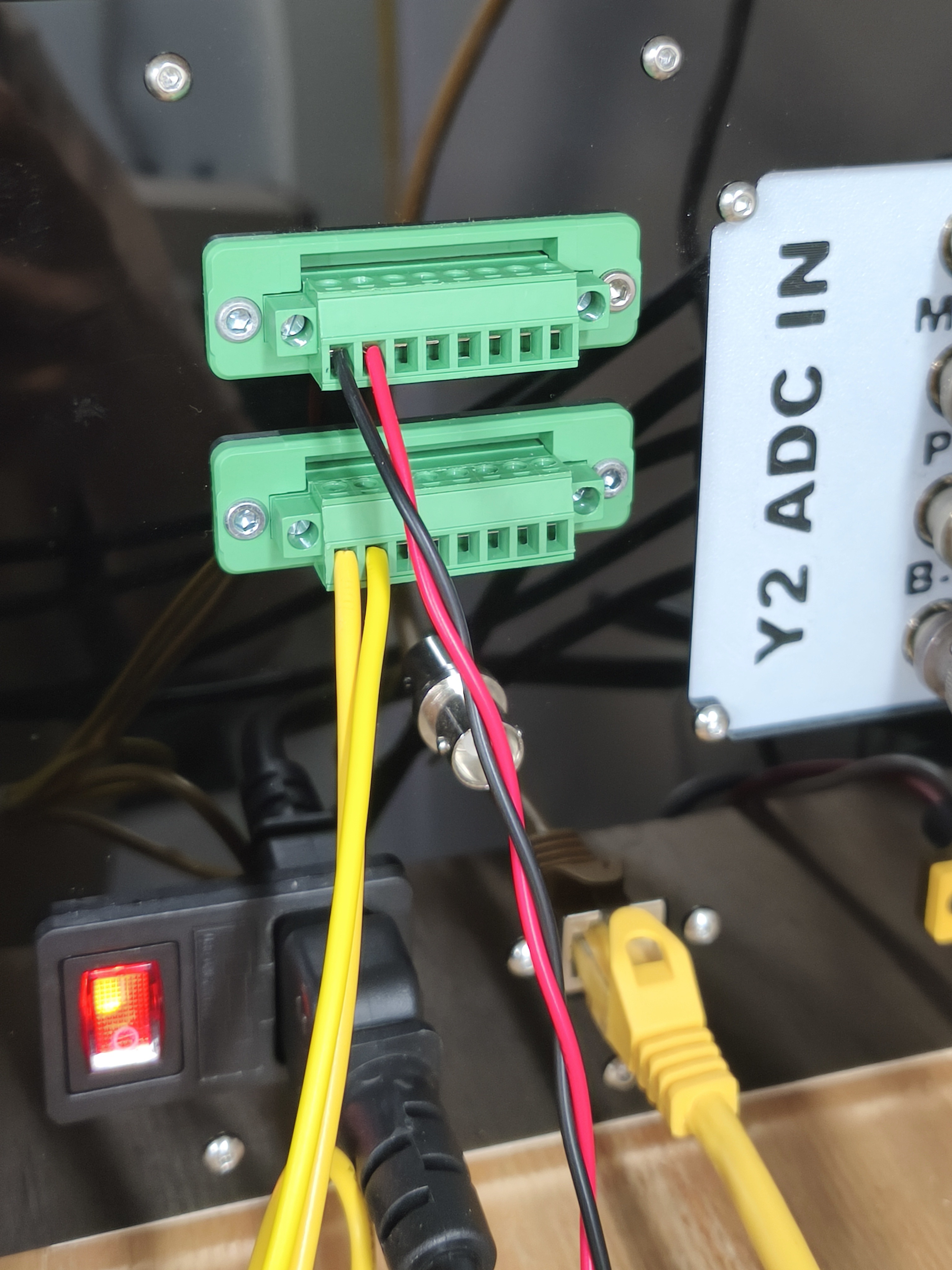
PIHTI Log, 2026-09-30, 17:35–17:50: the Kikusui control cable had been left unplugged after work on the box. The owner then recorded the correct port assignment above and a successful plasma run. At 17:50, a 1800 mV cathode command accompanied measured PSU output of 6.8621 V / 15.5079 A.
The LAN Output indicator reports the PSU's output-enable state; it does not prove that the analog control cable is connected or that power is flowing. Likewise, the cathode drive value is a software command, not a measurement at J1. Check the physical connection before diagnosing an enabled PSU with near-zero measured output as a webserver or supply fault.
PID
A plasma current in amperes (0–3 A). The plasma current PID, which runs
inside the ADC reader thread, moves the DAC every sample to hold the
measured Ip at the setpoint. "PID off" drops the DAC to zero.
Because the loop runs in the reader, it stops moving when the reader stops. From 4.11.0 the reader retries a failed read instead of dying, and the main thread writes "Reader lost" to the log if samples stop anyway; before that, a dead reader meant "PID on" moved nothing, which read at the rig as the supply not answering (2026-09-09).
Manual
A voltage in millivolts (0–5000) held on the DAC with the PID off — the
knob, in software (owner direction 2026-09-09). The filament sits where a
person put it whatever the plasma does, and the drive is written from the
main thread straight to the DAC worker, so it works while the reader is
lost. The web Control tab offers ±1000/100/10/1 mV draft steps and a Set,
as the gas rows do. The log line is "Cathode drive set to N mV, PID off",
and the web record's cathode_mv carries what the DAC holds, whichever
mode put it there; /api/health says outputs live: cathode drive while
it is not zero.
Until 4.11.0 this row was the Settings dock's "Output voltage" in volts, on the rig's screen only.
The supply's own knob
The Kikusui obeys its external input only while its CONFIG parameter
CF10 (Ext. CC) is ON; with CF10 OFF the front-panel CURRENT knob sets
the current again, whatever the DAC holds. So to run the cathode by hand
with the Raspberry Pi out of the loop: turn the drive off in the program
(or stop acquisition), then on the supply press CONFIG, turn the VOLTAGE
knob to CF10, turn the CURRENT knob to OFF, and hold CONFIG until the
measured values return. The change applies at once. CF11 is the same
switch for voltage control and CF12 the input range (Lo, 0–5 V, the
factory setting: output current = 40 A × Vext / 5 V at the
supply's own input). Set CF10 back to ON to hand control to the program
again. The manual pages are scans in the lab vault under
Hardware/Equipment/Kikusui Power Supplies.md, and the lab's own page is
aklab-howto.
Logging its voltage and current
From 4.15.0, optional read-only LAN logging writes the supply's measured
voltage/current to a separate timestamped file beside each acquisition.
Manual drive and PID behaviour are unchanged. The old ADC Ci/Cv values
are not LAN measurements. Setup, file fields and the loss-of-connection
behaviour are described in Kikusui over LAN.